


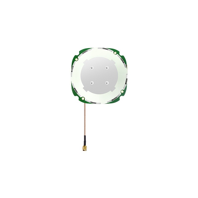
A practical guide to choosing among choke ring, survey patch, helical, and embedded designs
An rtk gnss antenna is the component that turns a satellite signal into a phase measurement stable enough for centimetre positioning. It is not a passive accessory to the receiver; it is the reference point from which every RTK solution is computed. When the antenna's phase centre moves, the reported position moves with it, and no amount of receiver processing recovers the difference.
This guide covers the main antenna types and where each one fits, the technical characteristics that distinguish a precision antenna from a general-purpose one, the applications that drive demand in each category, and a straightforward process for selecting and installing the right model.
What an RTK Antenna Does That a Positioning Antenna Does Not
A navigation antenna only has to deliver enough signal for the receiver to decode the broadcast ephemeris and compute a pseudorange. An RTK antenna has to preserve the carrier phase with sufficient fidelity that the receiver can compare it with a base station's phase and resolve integer ambiguities.
That requirement raises three properties above the ones that matter for navigation. The phase centre must be stable and well defined. The polarisation purity must be high enough to reject reflected signals, which arrive with the opposite sense of circular polarisation. And the group delay must be consistent across the band, so that different frequencies are not delayed differently as they pass through the antenna and filtering.
An antenna that satisfies those three properties can be used with a modest receiver and still produce good results. An antenna that does not cannot be rescued by an expensive receiver.
The Main Types and Where Each Fits
| Type | Characteristic feature | Typical use |
|---|---|---|
| Choke ring | Concentric rings suppress ground-plane currents | Reference stations, deformation monitoring |
| Survey patch | Multi-feed element on a defined ground plane | RTK rovers, base stations, machine control |
| Helical | Wide beam, compact, tolerant of motion | UAVs, robotics, high-dynamic platforms |
| Embedded or internal | Small element integrated into a host product | Handhelds, trackers, compact terminals |
| Combo | GNSS plus cellular or Wi-Fi in one housing | Telematics, fleet terminals, remote assets |
The choice is driven by the environment, not by a hierarchy of quality. A helical antenna on a moving vehicle is often more accurate in practice than a choke ring antenna, because the wide beam keeps satellites visible as the platform pitches, and the vehicle rarely operates in the severe multipath conditions that justify a choke ring.
The Technical Features That Matter
Band coverage
Modern RTK engines use multiple frequencies to estimate ionospheric delay and to speed ambiguity resolution. An antenna that covers only L1 limits the receiver regardless of its capability. The useful baseline today is coverage of BDS B1/B2/B3, GPS L1/L2/L5, GLONASS G1/G2/G3, and Galileo E1/E5a/E5b, with L-Band coverage where correction services are used.
Gain at low elevation
Satellites near the horizon are the ones most likely to be blocked, and they are also the ones that improve geometry when the sky view is restricted. Antenna gain that holds up at 10 to 20 degrees elevation contributes directly to availability in obstructed sites. Peak zenith gain is a less useful figure.
Phase centre stability
Survey-grade antennas are specified with a phase centre offset that can be entered into the software. What matters operationally is repeatability: whether successive units and successive temperature cycles produce the same offset. A well-defined but drifting phase centre is worse than a slightly larger but stable one.
Multipath rejection
Multipath rejection comes from three things working together: the ground plane geometry, the polarisation purity of the element, and the ability to suppress currents on the plane's surface. Choke rings address the third directly. The result is measured as a reduction in phase error under reflective conditions, not as a single decibel figure.
Mechanical and environmental characteristics
An RTK antenna usually stays installed for years. A cast aluminium base, a UV-stabilised radome, IP67 sealing, and a connector rated for repeated mating all contribute to the phase centre staying where it was on the day of installation. The mechanical design is part of the accuracy specification, not separate from it.
Applications That Drive the Requirement
- Surveying and mapping. Rovers and base stations use survey patches or choke ring antennas, with the choice determined by baseline length and the amount of nearby reflection.
- Deformation and structural monitoring. Permanent installations demand long-term phase stability more than any other specification, because the measurement is a comparison with the same station over months.
- Machine control and agriculture. Robust housings, vibration tolerance, and dual-antenna heading support grade control and autosteer on vehicles that work continuously.
- Autonomous vehicles and robotics. Compact helical or patch antennas with wide beams support navigation in environments where the sky view changes constantly.
- Timing and synchronization. Timing antennas prioritise group delay stability and environmental reliability over multipath performance in open-sky installations.
A Five-Step Selection Process
Selecting an RTK antenna
- Define the environment: open sky, urban, machine deck, or indoor transition.
- Define the accuracy requirement and the observation duration.
- Confirm the bands the receiver can use, and match the antenna to them.
- Check the mechanical envelope: diameter, height, weight, connector, mounting thread.
- Verify with a static test on the actual mount before committing to a quantity.
The last step is the one that most often changes the decision. An antenna that looks ideal on paper can underperform on a particular mount because the ground plane is smaller than assumed, or because a nearby structure creates a reflection path that the site plan did not show.
Installation Details That Protect Accuracy
Three installation practices account for most of the gap between laboratory performance and field performance. Mount the antenna on a metal surface at least as large as the specified ground plane, with a good electrical bond rather than a painted joint. Keep the antenna above the highest nearby metal edge, so that the pattern is not blocked at low elevation. And route the cable away from power conductors, with a drip loop before the connector so that water does not run into the housing.
For permanent stations, a lightning protection element and a proper mast grounding arrangement belong in the installation design. A station that is destroyed by a nearby strike takes its correction service with it, and the replacement cost is usually larger than the protection hardware.
Yonghao Innovation RTK GNSS Antenna Portfolio
Yonghao Innovation Tech is a national high-tech enterprise established in 2014, based in Shenzhen, Guangdong, China. We integrate research, manufacturing, and sales, and we supply GNSS satellite antennas, positioning terminals, data communication products, and customized high-precision BeiDou solutions for surveying and monitoring, aerospace, communication time service, autonomous driving, machine control, and intelligent transportation.
Our RTK GNSS antenna range covers the applications described above. The CM004 is a multi-system, full-frequency model with a dedicated choke and choke plate, high gain at low elevation, and IP67 sealing, intended for reference stations in cluttered environments. The YH-4N19A is a survey antenna covering BDS B1/B2/B3, GPS L1/L2/L5, GLONASS G1/G2/G3, and Galileo E1/E5a/E5b/E6 for general RTK work.
Where the platform is compact or fast-moving, the YH-502 provides a four-constellation full-band helical design in a small, light package. For permanent monitoring networks, the dedicated choke ring antenna range adds the models with the strongest multipath suppression. Vehicle configurations are described under autonomous vehicle projects.
Conclusion
Choosing an rtk gnss antenna is a matter of matching the element to the environment and the installation to the element. Choke ring, survey patch, helical, embedded, and combo designs each solve a different problem, and none is universally better. Confirm the band coverage your receiver can exploit, insist on phase centre data that reflects real repeatability, and test the chosen antenna on the mount it will actually use. That sequence produces a positioning system that holds its accuracy after installation, which is the only accuracy that matters.
Tell us the application, environment, and mounting surface, and we will narrow the antenna range to two or three candidates.
Get an antenna recommendation View all antennasFrequently Asked Questions
Q1: What is the difference between an rtk gnss antenna and a normal GPS antenna?
An RTK antenna must preserve carrier phase with a stable phase centre, high polarisation purity, and consistent group delay. A navigation antenna only needs enough signal to decode the message and compute a pseudorange, so its phase behaviour is not specified to the same standard.
Q2: Which rtk gnss antenna type suits a reference station?
A choke ring or a survey-grade patch with a large, well-defined ground plane. The choke ring is preferred where reflections from buildings, masts, or terrain are significant, because its geometry suppresses the surface currents that carry multipath into the phase measurement.
Q3: Does an rtk gnss antenna need a ground plane?
Yes. The ground plane is part of the antenna, not an accessory. Reducing its diameter below the design value lowers low-elevation gain, tilts the pattern, and can shift the phase centre, all of which reduce effective accuracy.
Q4: Can an rtk gnss antenna improve a receiver that is only single-frequency?
It can improve signal quality and multipath rejection, but it cannot create the second frequency the receiver needs to estimate ionospheric delay. The accuracy ceiling is set by the receiver's capability, and the antenna can only help the receiver reach it.
Q5: How often should an rtk gnss antenna be replaced?
There is no fixed interval. Replace it when the radome shows cracking or persistent water retention, when the connector no longer mates reliably, or when a static test shows phase noise that was not present at commissioning. A well-sealed antenna on a stable mount typically lasts many years.